+8613963751807
Installation von vertikalen kryogenen LNG-Großlagertanks
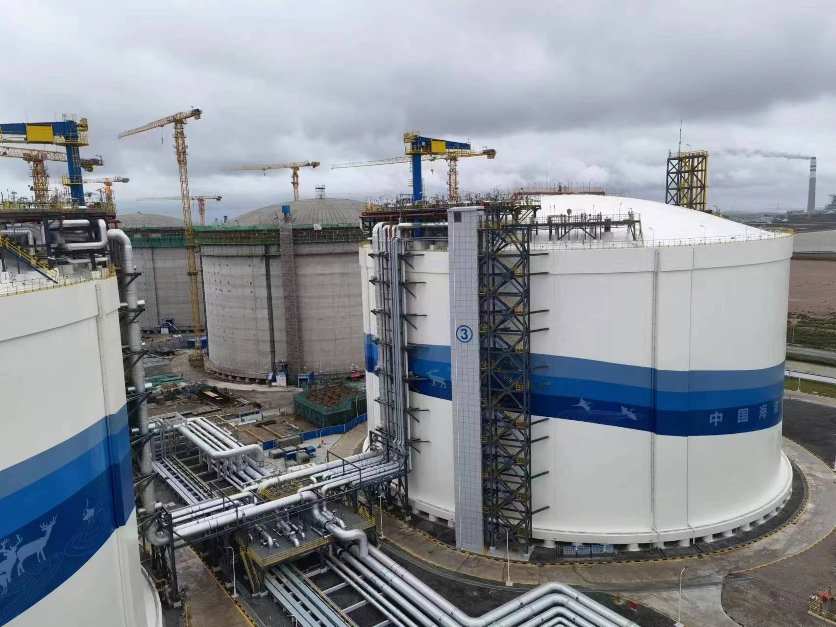
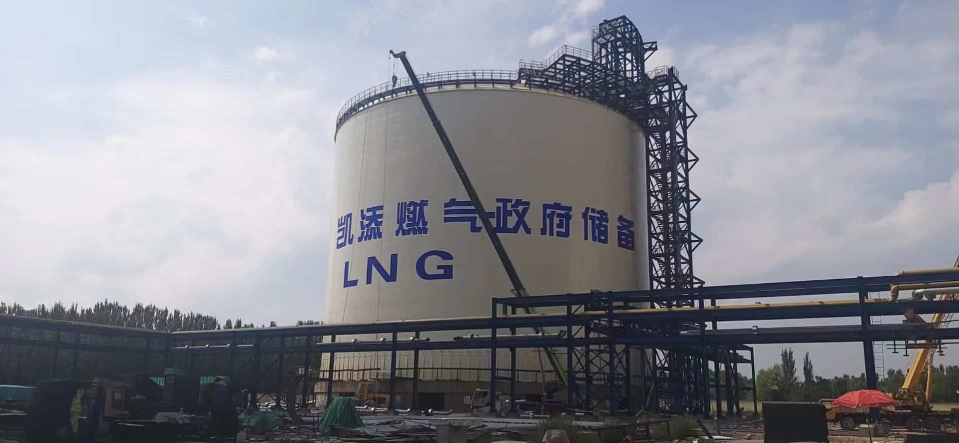
Installation von vertikalen kryogenen LNG-Großlagertanks
Category: Vertikaler Einbau von Lagertanks
Prefabrication processes such as cutting, trimming, rolling, and arc-bending for the outer tank shell plates and the inner tank wall plates of the LNG storage tank are conducted at the factory. Sandblasting and anti-corrosion coating for the outer tank are performed on-site. All prefabricated components are inspected against design drawings and relevant standards/specifications prior to…
Get Best Price
Don’t see what you’re looking for? Let us help you. Give us a WhatsApp or send us a message.You can contact us by:
I. Basis of Compilation:
-
API 620 Design and Construction of Large, Welded, Low-Pressure Storage Tanks
-
ASME Boiler and Pressure Vessel Code, Section IX Welding, Brazing, and Fusing Qualifications
-
EN 14620-2006 Edition
II. Installation Methodology:
-
This project is designed by a specialized design institute, with on-site installation undertaken by an installation contractor. The outer tank materials are delivered as raw stock, while the inner tank components are semi-finished, with cutting and beveling completed.
-
Prefabrication processes such as cutting, trimming, rolling, and arc-bending for the outer tank shell plates and the inner tank wall plates of the LNG storage tank are conducted at the factory. Sandblasting and anti-corrosion coating for the outer tank are performed on-site. All prefabricated components are inspected against design drawings and relevant standards/specifications prior to shipment from the factory, with corresponding construction records and inspection reports generated. For tank wall plates, inspections shall be conducted simultaneously using three methods: full-scale layout, arch height measurement, and template checking. Tank wall plates are transported using special cradles. Small prefabricated parts are packaged in containers or bundled for transport, clearly marked with the part name, quantity, and other relevant information.
-
The LNG cryogenic storage tank features a double-wall structure. Construction involves numerous sequential and interlinked procedures—material inspection/acceptance, prefabrication, assembly, welding, testing, and insulation—with significant crossover work. The schedule is tight and the workload substantial.
-
The minimum thickness of the inner tank wall plates is only 8-10mm, making them highly susceptible to welding distortion. Effective anti-distortion measures must be implemented during construction to ensure proper tank geometry.
-
The inner tank is constructed from materials such as 06Ni9 and 304 stainless steel, requiring nickel-based welding consumables. Furthermore, 100% Radiographic Testing (RT) is mandated for the inner tank welds. Consequently, a highly skilled welder workforce is essential, necessitating advance planning for welder training and qualification. Automated welding technology may be employed.
-
The variety of materials used for the inner and outer tanks necessitates a corresponding variety of welding consumables, imposing stringent requirements on welding material management.
-
This project involves a single-containment, double-walled metal insulated storage tank. The interdependent structure of the inner and outer tanks requires multiple construction techniques on-site. For example, the outer tank may be constructed using the “lift and shift” (倒装法) method, while the inner tank could be constructed using either the “climbing platform” (罐壁内挂钢平台正装法) method or the “lift and shift” method.
-
Construction of the Outer Tank Bottom
After foundation acceptance, four perpendicular baseline lines are established radiating from the foundation center point. The installation position lines for the annular plates are then laid out. The circumferential line for the annular plate installation position must account for shrinkage of the annular plate butt welds (calculate 4-5mm longitudinal shrinkage per annular plate weld joint). An installation reference circle is established using the enlarged diameter. The layout lines for the middle plates are based on the central strip plate.
Laying of the Outer Tank Bottom Plates
Annular plate joints are butt joints with backing strips. Middle plate joints are lap joints. The joint between the annular plates and middle plates is a lap joint. The lap width for middle plates is 45mm, and 60mm for the annular-to-middle plate joint. As butt joints are used and the tank bottom foundation is asphalt sand, the underside of the tank bottom does not require anti-corrosion coating per design.
Fit-up and Welding of the Outer Tank Bottom
After adjusting the lap amount, middle plates are fit-up and tack-welded. Tack welding should ensure tight contact between the lapped plates. For three-plate overlap areas in lap joints, a corner cut shall be made in the top plate. The cut length should be twice the lap length, and its width should be two-thirds of the lap length. Before laying the top plate, the fillet weld covered by the top plate should be welded first.
For annular plate butt seams, every five plates are first assembled and welded as a unit, leaving five contraction seams for final welding. Annular plate butt seams must meet drawing requirements, with a misalignment ≤1.6mm. The root gap is 4-10mm (4mm inner side, 10mm outer side).
Inspection of the Outer Tank Bottom
① Refer to the Welding Technical Procedure for Non-Destructive Examination (NDE/Inspection) requirements.
② Inspect ground-off areas from assembly tooling/welds for cracks or pits; repair welding is required if found.
③ Depth of weld undercut shall not exceed 0.4mm.
④ Both middle plate and annular plate welds must undergo 100% vacuum box testing at a test pressure not less than 53 kPa.
Vacuum Leak Test Method
After all tank bottom welding is complete and NDE is qualified, clean debris from the tank bottom and perform vacuum box testing on the bottom plate seams. A test vacuum of not less than 53 kPa is applied. No leakage is acceptable. A re-test is performed after the hydrostatic test.
Install one vacuum gauge each on the vacuum pump and vacuum box. Gauge dial diameter shall be ≥100mm, with a range of 0.1MPa and an accuracy class of 2.5. -
Inner Tank Bottom Structure and Construction
The inner tank bottom structure is similar to the outer tank bottom. However, the inner tank bottom is elevated 650mm above the outer tank bottom. The space between the inner and outer tank bottoms is entirely filled with insulation material (foam glass and dry sand layer). The area beneath the inner tank annular plate consists of perlite concrete precast blocks. The inner tank annular plate butt welds are double-sided welds. Therefore, the inner tank annular plates should be laid on elevated supports to facilitate welding in the overhead position.
Installation of the inner tank annular plates shall commence after installation and inspection of the perlite concrete blocks on the outer tank bottom are complete.
Due to the properties of the insulation material between the two tank bottoms (it cannot get wet), its installation must employ effective waterproofing measures. Installation of the inner tank middle plates should proceed after the 650mm thick bottom insulation layer is installed.
Requirements for laying, fit-up, welding, and inspection of the inner tank bottom plates are the same as for the outer tank bottom. -
Construction of the Outer Tank Wall
The outer tank wall is constructed using the hydraulic jacking “lift and shift” method. First, install the tank wall compression ring, followed by the outer tank roof framing. Then install the outer roof plates and the inner tank roof. Next, install the top course of wall plates and the roof compression ring. Subsequently, install the remaining wall plate courses sequentially using the “lift and shift” method.
Determining the Assembly Position Line for the Wall Compression Ring
Installation of Hydraulic Jacking Equipment
The effective lifting height of the hydraulic jacking equipment must be greater than the width of the wall plate being lifted. The number of hydraulic jacking columns is determined based on the maximum lift weight. The maximum lift capacity per jacking column is ‘g’ tons. The number of jacking columns ‘n’ is calculated using the formula: N = ψ × G / g. Where: g = maximum lifting force per column; G = maximum lift weight; n = number of hydraulic jacking columns arranged; ψ = safety factor, typically 1.2.
For LNG cryogenic tank outer tank “lift and shift” construction, hydraulic jacking equipment with 35-50 ton capacity jacks is selected. The maximum lift weight (including outer tank wall plates + compression ring + stiffening rings + outer tank dome + inner tank aluminum suspended ceiling) dictates that using multiple hydraulic jacks fully meets construction requirements.
Hydraulic jacking equipment is evenly distributed on a circle inside the tank, 250mm from the tank wall. Each hydraulic jack is radially braced with two inclined supports using φ89 steel pipes to enhance stability. Due to their smooth, fast, and safe operation, hydraulic jacking systems have become the preferred lifting tools for large dome roof tanks.
Fabrication and Installation of the Shoe Ring (胀圈)
The shoe ring is fabricated by rolling channel sections into an arc and welding them face-to-face. Channel section [25c is rolled to match the tank wall’s internal curvature precisely. The shoe ring can be made in 8-10 segments, tightened against the tank wall using 25-ton jacks. To prevent twisting and flipping of the shoe ring,龙门板 are installed on both sides of the shoe ring at each lifting column location. The hydraulic jacks lift the tank shell by lifting the shoe ring.
Dimensional Inspection of the Top Course Wall Plate Installation
Check the fit-up gap and misalignment of the wall compression ring and top course wall plates against drawing requirements.
Check the levelness of the upper edge of the wall plates. Measure two points per plate. Levelness deviation within any 9-meter length shall not exceed ±3mm. The difference between the maximum and minimum levelness around the entire circumference shall not exceed 9mm.
Assembly of the Second Top Course and Subsequent Wall Plates
Assembly of the second top course and lower courses proceeds after longitudinal and circumferential welds of the upper course are welded and NDE is qualified. Wall plates are positioned around the exterior of the upper course, and longitudinal seams are tack-welded, leaving one longitudinal seam temporarily un-fit. The tank shell is hydraulically lifted to the installation height, the remaining longitudinal seam is fit-up, and after welding is complete, the circumferential seam is fit-up.
Construction of Outer Tank Wind Girders and Stiffening Rings
Before installing wind girders and stiffening rings, re-measure and adjust the tank ovality until qualified. Wind girders and stiffening rings are prefabricated in segments. Mark and tack-weld positioning plates (using stiffener plates). Assembly should occur after longitudinal and circumferential welds of the corresponding wall plate course are welded and NDE is qualified.
Before installation, mark the installation position lines on the tank wall per design documents. The distance from wind girders/stiffening rings to circumferential welds shall not be less than 150mm. Where wind girders/stiffening rings intersect longitudinal seams, a semi-circular notch shall be made. No welding shall be performed within 50mm on either side of the notch.
Construction of the Outer Tank Shell-to-Bottom Fillet Weld
The outer tank shell-to-bottom fillet weld is fit-up and welded after the lowest course wall plate is assembled and welded. To prevent welding distortion, temporary internal bracing (L=1m, [10 channel, spaced at 1.5m) is used. Welding of the fillet weld must meet drawing and standard requirements (refer to Welding Procedure). After visual inspection, perform vacuum box leak testing and pneumatic leak testing.
Installation of Temporary Access Opening in Outer Tank
After assembling the bottom course wall plates, the wall plate designated for the temporary access opening is temporarily not welded. After the access opening reinforcement is assembled and welded, cut the temporary access opening for material, equipment, and personnel entry/exit. The location and reinforcement measures for the access opening shall comply with construction drawings. -
Construction of Inner Tank Wall Plates
Inner tank wall plates are transported into the tank using trailers and placed on cradles to prevent loss of curvature over time. The first three courses can be installed using a mobile crane. Remaining plates are installed using electric hoists. For material-specific inner tank wall plate installation, follow the standard sequence below:-
Strictly control welding parameters per the qualified Welding Procedure Specification (WPS).
-
Install temporary wall plates at the temporary access opening location on the first course (temporary plate thickness ≥16mm, width same as regular plate).
-
Install the second course. First, mark the starting position of the second course plates on the first course per the plate layout drawing.
-
After installing at least three plates of the second course, use alignment fixtures to position the vertical seams and tack-weld.
-
Check verticality before welding.
-
Perform dimensional checks, then commence vertical seam welding.
-
Fit-up and tack-weld the first circumferential seam between courses. Remove the 3mm shim plates.
-
Commence welding of the first circumferential seam.
-
After completing the circumferential weld for four wall plates, installation of the next course can begin.
-
After installing the fourth course and fit-up of its vertical seams is qualified, align the wall plate with the annular bottom plate and assemble the shell-to-bottom fillet weld. Before starting to weld the fillet weld, install temporary diagonal braces between the first course wall plate and the annular plate to prevent upward distortion of the annular plate during welding.
-
After tack-welding the vertical seams of the fourth course, commence welding the shell-to-bottom fillet weld. Welding should start from the inside, followed by back-gouging from the outside, then welding from the outside.
Installation of Inner Tank Wall Stiffeners -
Work platform layout should facilitate stiffener installation, welding, and NDE.
-
To reduce高空 work and accelerate progress, install stiffeners on single wall plates prior to wall plate installation. Leave a 1.5m long segment uninstalled at vertical seam locations. After the course is installed and vertical seam welding is complete, install the reserved stiffener segments.
-
The top course wall plate stiffeners are larger. Install them piece by piece after that course is installed and welded.
Closing the Temporary Access Opening in the First Course -
The temporary wall plate at the access opening is removed after the circumferential weld between the first and second courses is welded.
-
Close the tank wall temporary access opening after all wall plate and internal tank installation work is finished.
-
Before closing the opening with the正式 wall plate, complete the entire inner tank bottom vacuum leak test, remove all unnecessary materials from the tank, and thoroughly clean the tank bottom.
-
After welding the vertical seams of the正式 wall plate and passing NDE, tack-weld and weld the circumferential seam, followed by NDE.
-
Finally, weld the shell-to-bottom fillet weld at the closed access opening location. Perform 100% PT and vacuum box leak testing.
Wall Plate Assembly Quality Standards -
For plate thickness <6.4mm, maximum misalignment 6.4mm. For plate thickness >6.4mm, misalignment ≤25% of plate thickness or 3.2mm, whichever is less.
-
Angular distortion of longitudinal/circumferential seams ≤8mm.
-
Overall tank verticality ≤1/200 of height H (and ≤50mm). During assembly of each plate, verticality ≤4‰ of plate height H.
-
Local flatness deviation (peaking/buckling) ≤13mm.
-
-
Construction of the Outer Tank Dome Roof
The outer tank roof is installed after the tank wall compression ring is installed. The inner tank roof is laid out and welded on the outer tank bottom. After using hydraulic jacks to achieve the relative elevation difference between inner and outer tanks per drawings, install the inner roof hangers to suspend the inner roof from the outer roof main beams.
The outer roof mainly consists of a center crown ring, rafters, ring girders, and roof plates. The center crown ring, ring girders, and rafters are prefabricated H-beams assembled on-site.
Erection of the Outer Roof Center Temporary Support
To temporarily install the center crown ring, erect a temporary center support. The support is welded from steel pipes and angles, sized to the inscribed square of the crown ring. Its height is determined by the elevation difference between the crown ring and tank wall. Erect the center support after assembly and welding of the outer tank compression ring and after measuring tank diameter and ovality. It is removed after roof construction is complete.
Installation of the Roof Center Crown Ring
Hoist the crown ring to the top of the temporary center support. Ensure the elevation difference between the crown ring and the tank wall compression ring per drawings. Align the crown ring center with the outer tank bottom center, ensure the crown ring is level, then tack-weld it to the temporary support. Mark the installation position lines for the rafters on the crown ring.
Installation of Outer Tank Roof Framing
First, assemble sections of the outer tank dome framing on open ground outside the tank. Use a crawler crane to hoist these pre-assembled sections into the tank for installation. During hoisting, first对称吊装 large sections, then对称吊装 smaller sections. After installing the large sections, use elevating work platforms to install the ring girders connecting large and small sections, thereby completing the entire dome structure installation.
Construction of the Roof Plates
Lay and tack-weld the roof plates per drawing requirements. Plates should be laid symmetrically to prevent uneven stress causing roof deformation.
Construction of the Inner Tank Aluminum Suspended Ceiling (Al吊顶)
(1) The inner tank roof is laid out elevated on the outer tank bottom. To prevent direct contact between the aluminum roof panels and the outer tank bottom plate during laying and welding, first lay a layer of thin wooden blocks on the outer tank bottom to separate them. Then assemble and weld the aluminum roof panels on the outer tank bottom.
(2) After completing assembly and welding of the aluminum roof panels, weld the various circular stiffening rings distributed across the铝吊顶. Simultaneously, install the aluminum roof hanger rods connected to the dome rafters.
(3) The connection between the铝吊顶 hanger rods and the stiffening rings on the roof panels is made via bolts after the first course of the outer tank wall is hydraulically lifted to a suitable height. Holes are drilled on-site according to the actual dimensions of the rods and stiffening plates. As the outer tank “lift and shift” construction proceeds, the inner tank aluminum roof is lifted by the hydraulic jacks.
Installation Technical Requirements
(1) Both inner and outer roof plates use lap joints: Lap width for inner tank铝吊顶 middle plates ≥30mm; lap between middle plates and边缘板 ≥40mm. Lap distance for outer tank dome plates is 50mm.
(2) The orientation of inner and outer roof plates must comply with drawing requirements.
(3) Outer roof installation is checked with a template; gap shall not be less than 15mm (internal control target).
(4) After inner roof installation is complete,凹凸度 shall not be less than 50mm (internal control target).
(5) Grind smooth all tooling/attachment weld marks on the inner roof and inspect per requirements.
0
ABGESCHLOSSENE TANKPROJEKTE
0
Erfahrung in der Fertigung
0
QUADRATMETER PRODUKTIONSFLÄCHE
0
BELEGSCHAFTSEIGENTÜMER
Shandong Shijie actively expands its domestic and international markets, establishing long-term strategic partnerships with well-known enterprises such as PetroChina, Sinopec, Huaneng, and Geely. Its engineering projects cover more than 300 cities in 23 provinces in China, and its international engineering operations have reached nearly 30 countries and regions in the Middle East, Central Asia, Southeast Asia, Europe, and America, receiving widespread praise from domestic and foreign merchants. In the future, Shijie people will warmly welcome domestic and foreign merchants to create brilliant careers together!


Do You Have A Question?
We are happy to answer any of your questions relating to our inventory, locations or the way we do business.
Looking for a quote?
We recommend you submit a request for quote document via our RFQ Form.
Fordern Sie ein Angebot für Ihr nächstes Projekt für oberirdische Lagertanks an.